Note that the parts lists are in an erratic order.
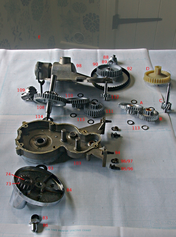
Exploded diagram of Kenwood gearbox with TDA part numbers. Check the parts with the Service manual (above) before ordering - especially the "assemblies":
|
|
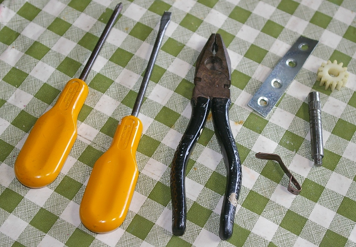
Tools and parts used for my Chef repair. See Step 6b for the picture hook.
|
|
|
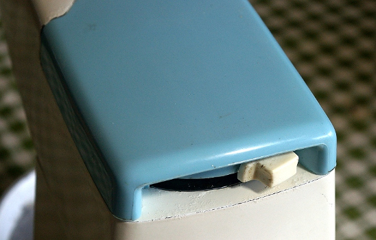
Step 1. Remove the liquidiser cover. |
|
|
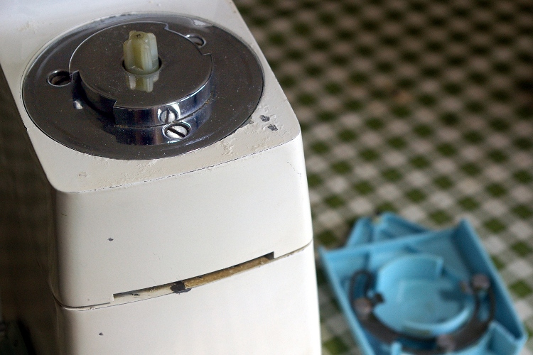
Step 2. Unscrew the chrome plate which is the high-speed drive outlet with a 7mm flat-head screwdriver. |
|
|
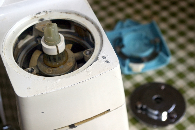
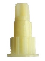
Step 3. You have now exposed the high-speed spigot or liquidiser pulley which is attached by a pin (if you need to remove it). On the right is a picture of the spigot itself. |
|
|
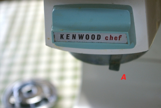
Step 4. Push the outlet catch A to allow you to remove the slow-speed outlet cover above. Now pull (or lever) off the plastic end of the catch A. |
|
|
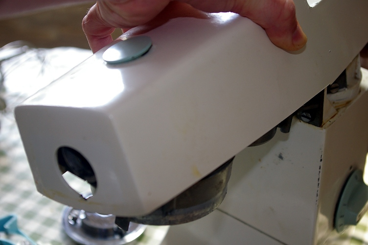
Step 5. Remove the cover, with the citrus juicer cover / stopper still attached. |
|
|
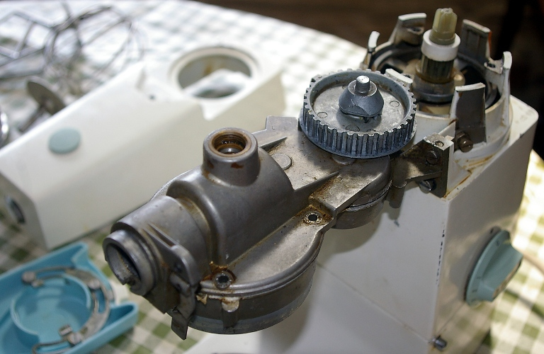
Step 6. Ease off the toothed rubber drive belt (or drive pulley belt) by pulling it upwards whilst rotating it. The dog clutch and large pulley can now be removed (see below). |
|
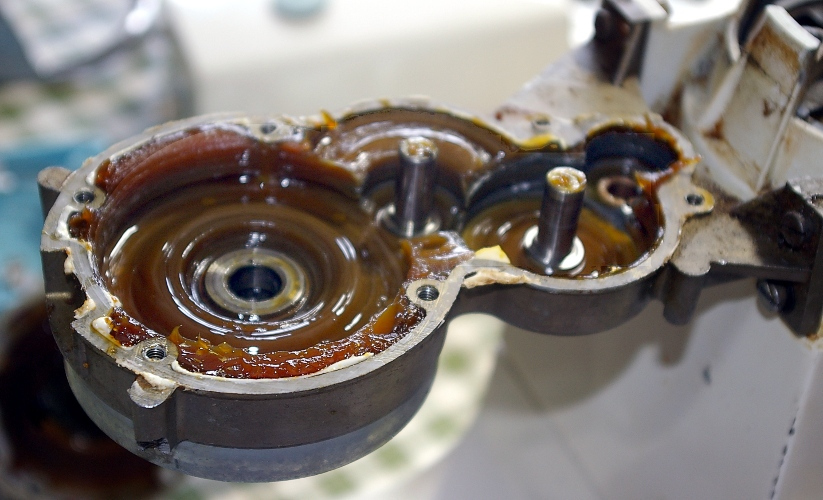
The dog clutch.
This is a rather tacky mechanism which produces a large part of the noise from your Chef. To do any testing of the system whilst the liquidiser cover is not in place, you will need to press down on the gear using something like the flat of a pair of pliers. Be careful not to slip whilst doing this. Rupert Wheatstone (see above under parts suppliers) says "(This technique) scared the life out of me - what you need is a soft plastic implement with a hole filled with grease, so that you can press down on the dog before switching on the machine - don't forget to remove the gearbox lock!" To over-ride the operation of the dog clutch, or if the clutch is worn, see this How To Mend It item.
| |
|
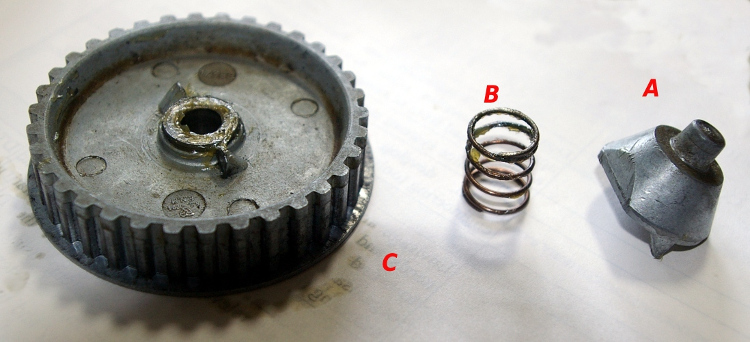
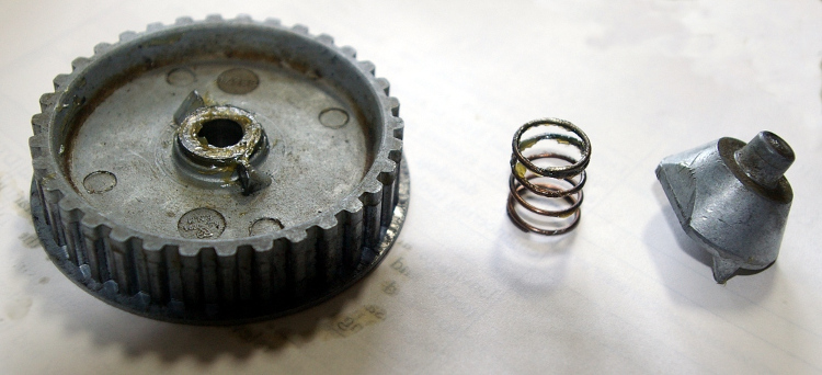
Step 6a. To remove A - the dog clutch gear you will need to unscrew it whilst stopping the gears. For the following guidance, I'm indebted to David and Lana at Lana's Kenwood spares (see above). To stop the gears, first remove the planetary orbit hub drive (see separate section below).
Place a adjustable spanner on to the D shaped shaft. If the gears are stopped and the dog clutch gear doesn't unscrew, then your drive pinion gear is probably plastic and slipping. See Step 6b (below) in this case. Under the dog clutch gear is the B - dog clutch spring and the C - large pulley which can now be lifted off. |
|
|
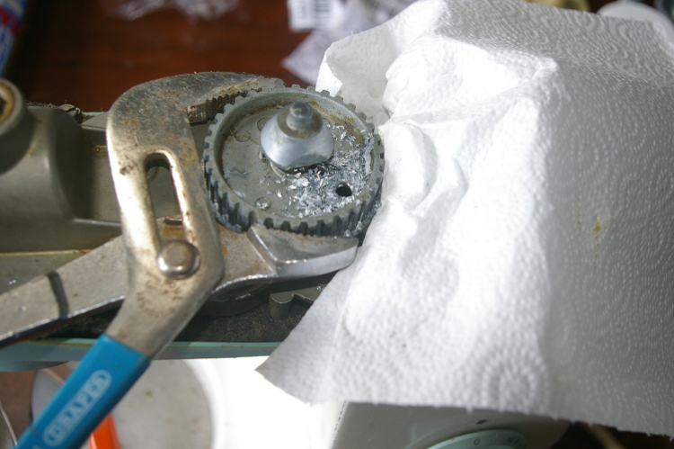
Step 6b.
This step is only required if Step 6A (above) fails. If this doesn't work then you can try drilling a hole (as suggested to me by Brian Norris and Alan Diver), just big enough for your screwdriver (I used a 6.5mm bit), above the screw, through the pulley below the dog clutch (C above). The outer edge of the small round indentations is the correct place for a hole. Obviously, you will need to be careful to:
Rupert Wheatstone (see above under parts suppliers) advocates the following technique - "In order to separate the gearbox halves, you need to wedge up the pulley, (as above), but then adopt another, more elegant solution to removing the two troublesome screws - as an alternative method to 'chiseling' the heads round and spoiling the heads - you could ... use a low profile screwdriver bit with a flange and a square drive turned by a flat spanner with a square hole. To loosen, before removing with long nose pliers - an alternative would be a screw driver bit turned by a flat spanner with a hexagonal hole, albeit a little wobbly." |
|
|
Step 7. You can now unscrew the upper gear box case but don't lose the locking washers. The upper case should lift straight up. If your Chef has been recently serviced, etc. then the silicone seal around the bottom edge of the upper case may hold it and you may have to be more firm in your lifting! |
|
|
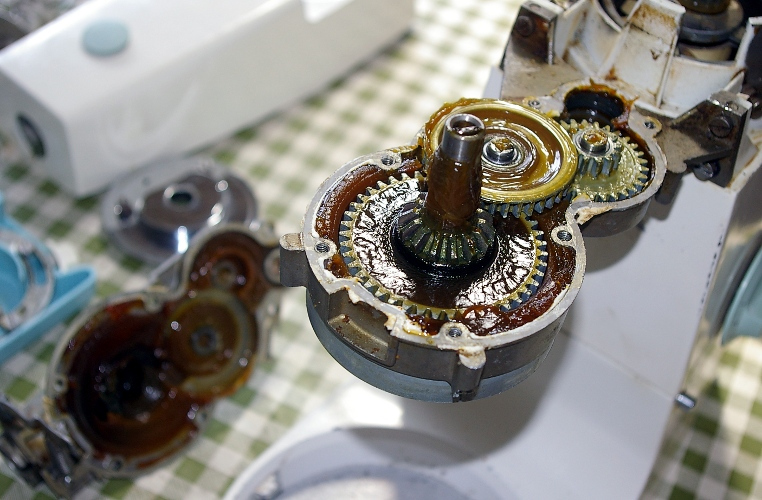
Step 8. Pull the gears up, but keep them in order and especially don't lose their washers. What remains is the Lower gear box case. |
|
|
Step 9. A is the original plastic-geared (split and slipping) "drive pinion gear". B is the new metal-geared (works fine now) "drive pinion gear". C is the "intermediate gear or 2nd. drive gear". D is the "penultimate gear or 3rd. drive gear".
|
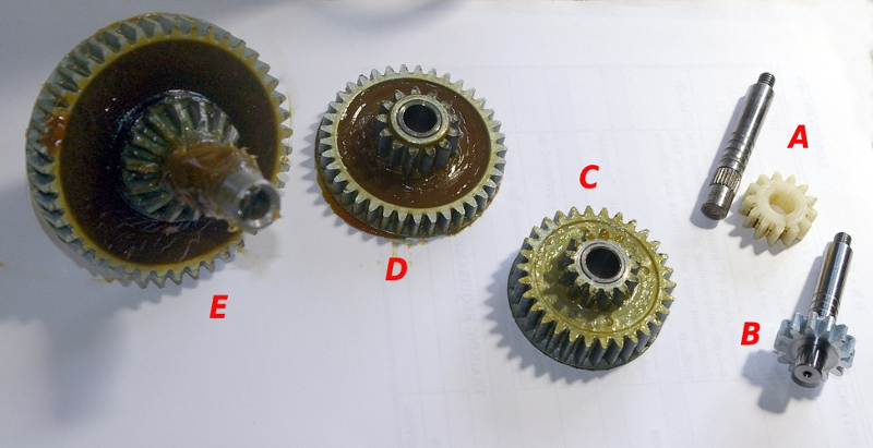
Watch out that you don't try to fit angled gears when the 701 normally has straight ones. |
|
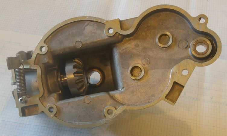
Step 10. Now you can access the slow speed outlet gear which can come out by pushing it into the cavity. |
|
|
Step 10a. This is the stage at which you may want to clean out all the old grease.
To help with this, it is easier to remove the Lower gear box case. The nuts and bolts holding this are quite tight and require an 8mm spanner.
You will need to scrape out as much as you can - watching out for washers stuck in the grease.
| |
|
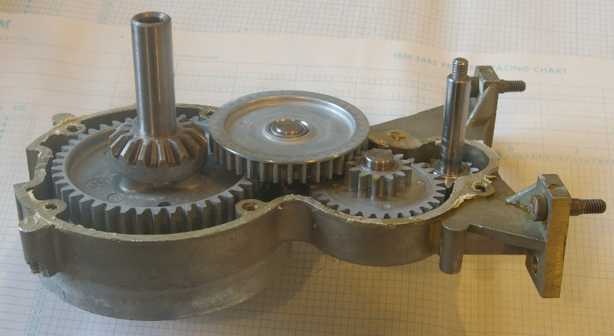
Step 11.
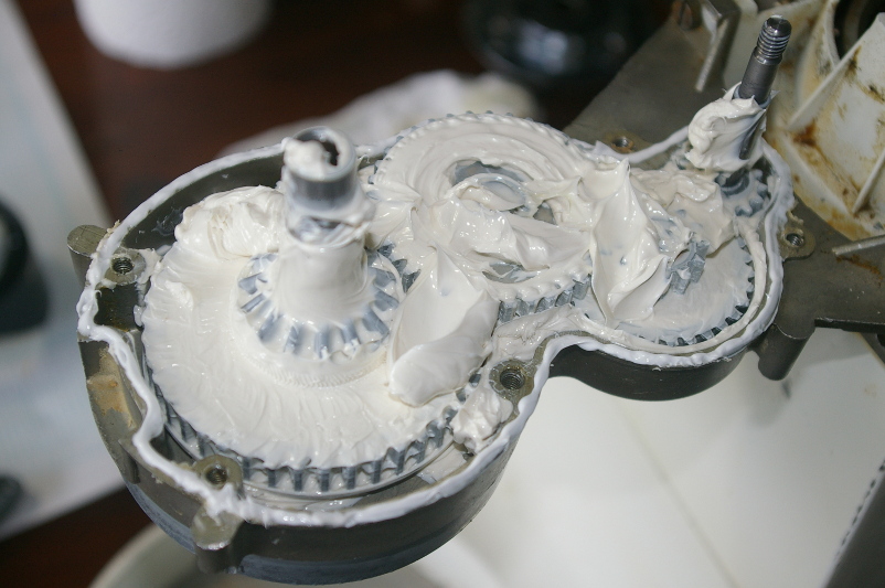
Now you come to reassembly. Now refit the gears on their spindles (not forgetting the washers and plenty of grease - see next photo). You'll see that I've removed the gearbox from the rest of the mixer - to make working on it easier. For all you food photographers - try using a small aperture to get everything in focus! (sorry, pet hate). |
|
|
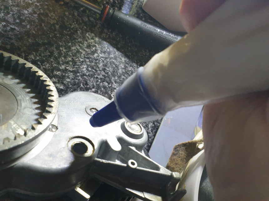
Step 11a. This shows topping up the gearbox grease with an icing tube and disposable bag, enabling getting the grease into those awkward spots. Thanks to Mike French of Perth, Western Australia, for the technique. |
|
|
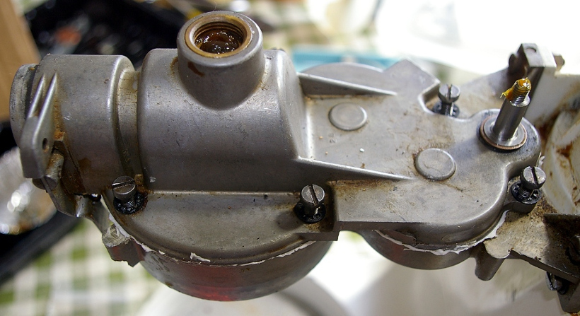
Step 12. Clean off any spilled grease around the edge of the casing and apply silicone seal around the edges of the gear box. A small tube of silicone makes this easier than with the regular DIY type. N.B. Don't leave any spills inside where it can get into the gears. You may wish to leave the gears out whilst doing this but that's up to you. Apply a quite thin bead all round - somewhat less than James May did on TV since too much may squeeze into the gears. |
|
|
Step 13. Refit the top gearbox cover and do up the screws (not forgetting the locking washers). It is safest to do them up as you would a cylinder head - first doing them all up gently and then going round tightening them up. Don't do them up so tight that you crack the cover. |
|
|
Step 14. Refit the dog clutch components. |
|
|
Step 15.
This is the slow-speed outlet showing the mechanism of the release lever. |
|
|
Step 16.
Refit the "toothed rubber drive belt" by the reverse of how you took it off (step 6). |
|
|
Step 17. Replace the top cover, with the citrus juicer cover / stopper. Try to find the plastic end of the outlet catch for the slow-speed outlet cover and re-fit it. The outlet catch is shown in the picture for Step 22 (below). Replace the chrome plate on the high-speed drive outlet (see picture on right which shows the correct way round). |
|
|
Step 18.
Fit the lower gearbox felt cover, being careful to align the four holes with the screw holes on the casing. N.B. The holes are different for each side so check which way up you have it. |
|
|
Step 19. Replace "lower gearbox cover" but be careful of the screws which will break the casing into which they connect if over-tightened (even a little). |
|
|
The planetary orbit hub drive - version with chrome cover. If yours has a plastic cover, see the next section. | |
|
Step P1. This shows the planet hub assembly. To remove it, undo the planetary orbit chrome nut and then gently pull down / lever off the assembly. |
|
|
Step P2. This is the inside of the planetary orbit hub drive which I didn't need to remove for my Chef repair, but I did so to check it was OK and well lubricated. In the centre is an out-of-focus view of the D-shaped shaft. |
|
|
Step P3. This is the planetary orbit hub drive with its planetary orbit hub drive gear cog and the planetary orbit chrome nut on the right. The three studs Hold felt washers on some mixers (thanks to Allan Wayte for this information) |
|
|
Step P4. Apply a blob of grease and then replace the planet hub assembly. This should push up into place. Check the planetary orbit chrome nut before refitting to see if it has a rubber washer which may need cleaning. Do up the nut with a spanner - but not too tight. |
|
|
The planetary orbit hub drive - version with plastic cover. This section courtesy of Charlie Riddock.
| |
|
Step Q1. This shows the planet hub assembly. To remove it, undo the planetary orbit chrome nut and then gently pull down the cover. |
|
|
Step Q2. This is the inside of the planetary orbit hub drive which it is best to open up so as to check it is OK and well lubricated. |
|
|
Step Q3. This is the planetary orbit hub drive with its planetary orbit hub drive gear cog. In the centre is the D-shaped shaft. |
|
|
Step Q4. To re-assemble, place the rotary arm on the D-shaped shaft and push up, making sure the cog engages as shown. Replace plastic cover, which should push up into place. Check the planetary orbit chrome nut before refitting to see if it has a rubber washer which may need cleaning. Do up the nut with a spanner - but not too tight. |
|
|
The planetary orbit hub drive rivets. This section largely courtesy of Charlie Riddock.
Here we deal with the rivets holding the planetary gear housing to the lower gear box casing, which can shear. When the motor runs and the unit powers the dough hook, the lowest gear housing also rotates, rendering the dough hook useless. But you can't see this until the lower part of the planetary hub is removed. If this has happened to your Chef, then I have only heard of one way of replacing the rivets - see below.
If you don't want to try this method, then you will have to replace the whole lower gear housing. You can't simply put new rivets in place as these would foul the inner cog rotation as it all sits flush. See at the top for a list of suppliers. | |
|
Step R1. This shows how the planetary gear pulls down from the gearbox - if the rivets are broken.
|
|
|
Step R2. Here is a view of the inside of the lower gear box, from above, with the broken rivets pushed up from the under side to show them clearly.
|
|
|
Step R3. This shows the plate (from inside the gearbox) which should be held down by the rivets. It shows the tear out of the broken 'cast rivets'. (Meaning they can't be drilled out and new rivets inserted). |
|
|
Step R4. This is the planetary gear which should be clamped to the gearbox by the rivets. See the picture in Step Q4 above which shows how the rotary arm and cog sit flush, explaining why you cannot replace the broken cast rivets with new rivets. And now for the fix, for which I'm indebted to Piers Butterfield - "What I did ... was to drill out the six holes to a close fit to M5 (possibly M4) and in fact I drilled out another 6 holes, then countersinked the underside and fitted twelve (possibly over-kill!) M5 countersunk posidrive-head screws in place (countersunk in order not to foul the planet gear). I think I ground them to length and used thin washers on the upper face so as not to foul with what was going on there. I was aware that if any of these screws came loose they could do a whole heap of damage, so did them up pretty tight and used Loctite as well as 'staking' the screw ends, all to try and keep them secure. The alternative would have been to put the screws in from above and thread the gear housing, but I wasn't convinced the cast metal would take the fatigue load. It's rather expensive if you're doing it professionally, but I got fed up with the rivets breaking! Sorry but I have no photos as it's all assembled now and has been working hard for approx 5 years. I took it apart recently to attend to the input gear, and all seemed OK although it is of course wearing..." |
|
And now, put all the left-over nuts, gears, screws, etc. in an envelope for safe-keeping.
Then let me know if the above helped, or if you found any mistakes (see below).
| |
This page last updated 23rd. October 2020.
Images and text © Copyright Jim Batten, 2014-2020. Some images © Copyright Charlie Riddock, 2015.